Thermal conductivity in liquid nitrogen pipes
29 April 2022
Thermal Conductivity Kt
The transfer of liquid nitrogen LN2 over any distance in a plant, whether indoors or outdoors will incurr significant economic loss of cryogen through evaporation and quality degradation of the cryogen delivered at the point of use. Under normal operational circumstances, the liquid in the system is constantly vaporizing into gaseous nitrogen due to constant heat leak. The amount heat leaks depends on the type of insulation method used and the difference can be as big as 50X. Therefore, plant facility engineer need to understand thermal conductivity value Kt of each insulation method during engineering evaluation before making purchase decision. In this article we will share some calculation example for Kt value in foam insulated pipe and vacuum insulated pipe.
Traditional Foam Insulated Transfer Piping
For decades, the accepted method of insulating cryogenic transfer pipe (typically copper or schedule 10s stainless steel pipe) was to use foam insulation covered by a protective polyvinyl chloride layer. This type of insulation is inexpensive and works well when new, providing typical heat transfer rates above 10 - 20 Watt/meter (BTU/hr/ft ) at LN2 temperatures. However, its performance deteriorate rapidly within five years, and becomes less effective in preventing vaporization of the liquid as the product ages.

If you are using liquid nitrogen (LN2) in your processing operation and your transfer lines are more than 5 years old, you might be losing money every day. You probably see ice spot or frost along the pipeline and a water puddle on the floor, but it won’t alarm you that something is amiss. Instead, what typically happens is that you will gradually use more and more LN2 with each passing year without even realizing.
The following theoretical model has been developed (Bootes & Hoogendoorn 1987) to predict the thermal conductivity of closed cell foams:

Vacuum Jacketed Piping
The technology in transfer piping for LN2 and other cryogenic fluids has made substantial advances since the early 1990s. Not only are today’s transfer lines better insulated to minimize the loss of LN2 through evaporation, but they are also easier to install and are virtually maintenance-free.
Two types of vacuum jacketed piping (VJP) systems (also referred to as vacuum insulated) — rigid and flexible — are available for process plant installations where long runs of piping are required to transfer LN2 from a bulk storage vessel at the back of the plant to one or several use points.
There are three modes of heat transfer:
Conduction - CSM VJP reduces conduction by using low conductivity radial supports to prevent the inner pipe from touching the outer pipe
Convection - is prevented by removing the gas molecules from the space between the inner and the outer pipe at high vacuum 10-5Torr
Radiation - the inner pipe is wrapped with multiple layers of reflective radiation shield and low conductive spacer material to reduce radiation.
Vacuum jacketed pipes are designed to overcome the above heat leaks, as diagram below shown.
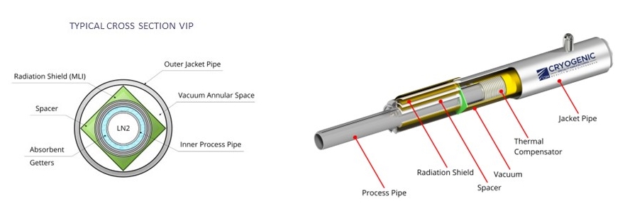
The inner pipe which carries the cryogenic liquid is wrapped with multiple layers of super-insulation material, consisting of alternating layers of radiant heat barrier material and non-conductive spacer material. Also, the vacuum annulus contains getter materials to absorb gas molecules to further improve the vacuum. Most importantly, the space between the two lines is evacuated and then sealed in a static vacuum system or by a on-site vacuum pump in dynamic vacuum system.


Conclusion
Thermal conductivity Kt value for in super insulation vacuum jacketed pipe is 50 times lesser compared to foam insulation.
Read more in the blog: super insulation
Back